This website stores cookies on your computer. These cookies are used to improve your website experience and
provide
more personalized services to you, both on this website and through other media. To find out more about the
cookies
we
use, see our Privacy Policy.
We won't track your information when you visit our site. But in order to comply with your preferences, we'll have
to
use just one tiny cookie so that you're not asked to make this choice again.
Proton exchange membrane conductivity measurement
Source:Corrtest
Time:2021-12-22
View:0
Proton exchange membrane fuel cells (PEMFC) use proton exchange membranes (PEM) as electrolytes, and their performance directly affects the battery performance, energy efficiency and service life of PEMFCs. The ion conductivity of proton exchange membranes is an important indicator of PEM performance.
In this paper, the EIS impedance technique is used for testing. The principle is: impose a small amplitude symmetrical sine wave electrical disturbance signal on the PEM electrochemical system and measure its response signal at the same time. The ratio of the response signal to the disturbance signal is called impedance or admittance. The real and imaginary parts of the impedance at different frequencies are measured, and a series of data points are obtained to form an impedance spectrum. Through the analysis of the impedance spectrum, the membrane resistance Rf and the membrane capacitance Cf can be calculated. Because the electrolytes do simple harmonic vibration in the equilibrium position under the alternating electric field, and the positive and negative ions will not move in one direction for a long time. The alternating electric field will also reduce the electric double layer on the electrode. Therefore, the influence of interface polarization is reduced, and the measurement result of membrane resistance is closer to the true value.
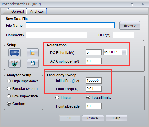
Using CS350 EIS potentiostat/galvanostat/ electrochemical workstation (Corrtest Instruments) for impedance measurement, the sine wave amplitude is 10 mV, the DC polarization amplitude is 0 V vs OCP, the scanning frequency range is 105~1Hz, 10 points/10 octave.
The test system is shown in Figure 1, in which two gold-plated copper plates are clamped by a strong spring clamp to ensure close contact between the copper plate and the membrane. The test results are shown in fig. 2 and fig. 3..png)
Fig 1. PEM conductivity test fixture
Using a micrometer to measure and obtain the thickness (T), length(L) and width(W) of the membrane, then calculate the ion conductivity of the PEM according to below formula (1):
.png)
According to the description in Figure 1, a perturbation voltage from 1 Hz to 100 kHz is applied to the proton exchange membrane (4), and then the response electrical signal of the PEM is read from the platinum electrode (3) at both ends, and finally the EIS plot of the PEM can be obtained, as is shown in fig. 2 and fig. 3.
The ion migration resistance R (50.6 kΩ) can be read from the intersection of the data point and the real resistance in the figure. .
.png)
Fig 2. 25% RH 25 ℃ EIS
.png)
Fig 3. 50% RH 25 ℃ EIS

σ = a /( R × b × d )(2)
.png)
.png)


Based on ion conductivity calculation formula specified in <GB/T 20042.3-2009>, ion conductivityσ = L /((590570 Ω )× b × d ).
In this paper, the EIS impedance technique is used for testing. The principle is: impose a small amplitude symmetrical sine wave electrical disturbance signal on the PEM electrochemical system and measure its response signal at the same time. The ratio of the response signal to the disturbance signal is called impedance or admittance. The real and imaginary parts of the impedance at different frequencies are measured, and a series of data points are obtained to form an impedance spectrum. Through the analysis of the impedance spectrum, the membrane resistance Rf and the membrane capacitance Cf can be calculated. Because the electrolytes do simple harmonic vibration in the equilibrium position under the alternating electric field, and the positive and negative ions will not move in one direction for a long time. The alternating electric field will also reduce the electric double layer on the electrode. Therefore, the influence of interface polarization is reduced, and the measurement result of membrane resistance is closer to the true value.
Using CS350 EIS potentiostat/galvanostat/ electrochemical workstation (Corrtest Instruments) for impedance measurement, the sine wave amplitude is 10 mV, the DC polarization amplitude is 0 V vs OCP, the scanning frequency range is 105~1Hz, 10 points/10 octave.
The test system is shown in Figure 1, in which two gold-plated copper plates are clamped by a strong spring clamp to ensure close contact between the copper plate and the membrane. The test results are shown in fig. 2 and fig. 3.
.png)
Fig 1. PEM conductivity test fixture
Using a micrometer to measure and obtain the thickness (T), length(L) and width(W) of the membrane, then calculate the ion conductivity of the PEM according to below formula (1):
.png)
According to the description in Figure 1, a perturbation voltage from 1 Hz to 100 kHz is applied to the proton exchange membrane (4), and then the response electrical signal of the PEM is read from the platinum electrode (3) at both ends, and finally the EIS plot of the PEM can be obtained, as is shown in fig. 2 and fig. 3.
The ion migration resistance R (50.6 kΩ) can be read from the intersection of the data point and the real resistance in the figure. .
.png)
Fig 2. 25% RH 25 ℃ EIS
.png)
Fig 3. 50% RH 25 ℃ EIS
From fig. 2 and 3, we can say that the resistance decrease with the increase of humidity on the surface.
Data analysis
Data analysis

Fig. 4 EIS equivalent circuit
Where, Rcont is the contact resistance between the membrane and the electrode. Because Pt is used as the conductor, this value is generally small, within 1Ω, Rfilm is the membrane resistance, Cfilm is the membrane capacitance, and Cdl is the double layer capacitance between membrane/Pt electrode. Rct is the electrochemical reaction resistance on the surface of the electrode, Wf is the Warburg diffusion resistance.
Rfilm can reflect the migration freedom of ionic groups (H+) in the membrane. The higher the activity, the smaller the Rfilm. Cfilm reflects the thickness of the PEM and the value of dielectric constant. The greater the thickness of the membrane, the smaller the Cfilm, and the smaller the dielectric constant (e) of the membrane (the lower the concentration of ionic groups in the membrane, the smaller the dielectric constant. ), the smaller the capacitance value. Cf-T generally reflects the uniformity of ion channel distribution in the membrane. The more uniform the internal structure of the membrane, the greater the value.
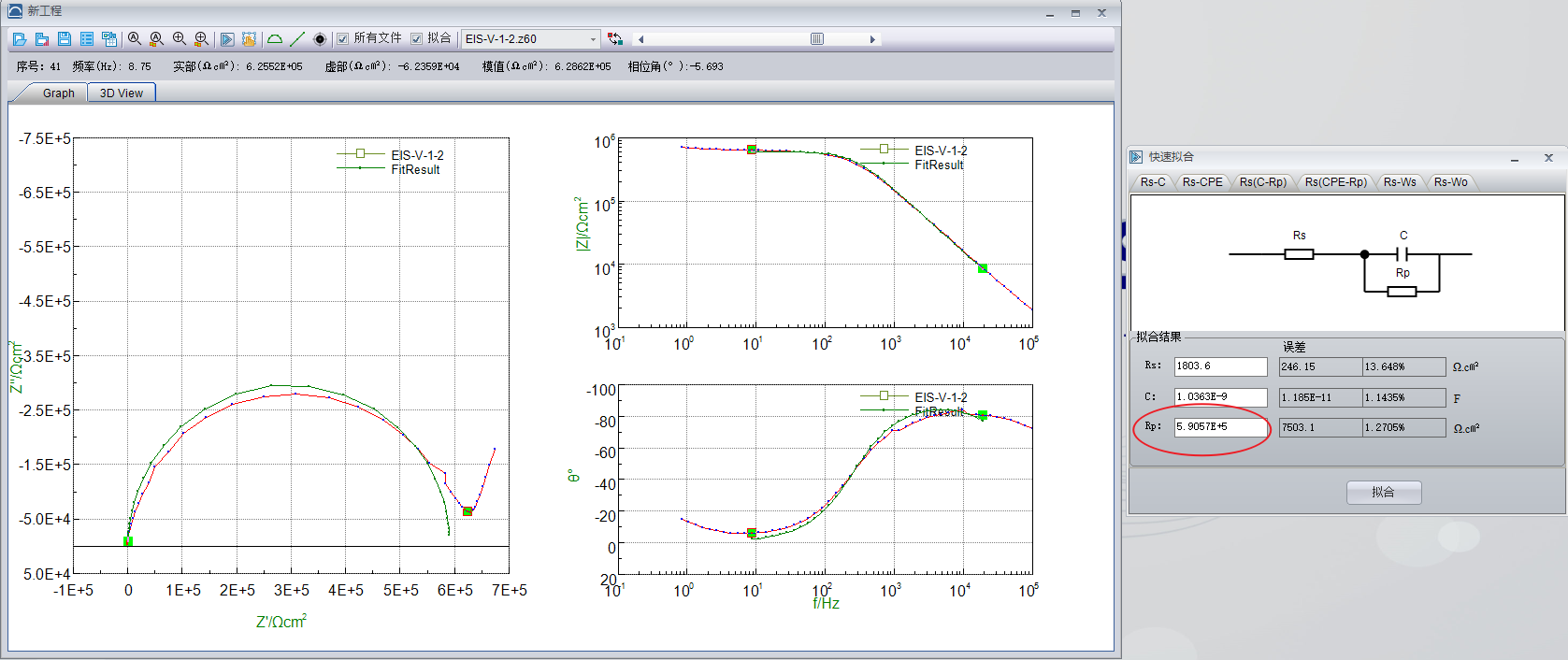
According ti GB/T 20042.3-2009, in the measured impedance spectrum, read the impedance value (R) of the sample from the intersection of the high-frequency part of the spectrum and the real axis, and calculate the ion conductivity of the sample according to formula (2).
Where,
σ—ion conductivity unit is S/cm.
a— the distance between two electrodes, unit is cm.
R—the measuring resistance of the sample. Unit is Ω.
b—the effective length of the membrane that is vertical to the electrode. Unit is cm.
d—the thickness of the sample. Unit is cm.
Experiment
Samples:PEMs (Shangdong Dongyue)
Technique: EIS vs. Frequency
Instrument:CS350 EIS potentiostat (Corrtest instruments)
Sample holder: Film conductivity test fixture, as follows
.png)
- Experiment steps
- Assemble the PEMs on the fixture, cover the upper cover and tighten the screws. Using our electrode/cell cables to connect the samples.
.png)
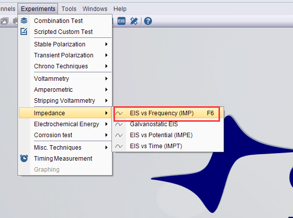
- Choose technique EIS vs. Frequency, and set the parameters.


- Data analysis
According to the data analysis shown in below, the membrane resistance can be obtained.

Based on ion conductivity calculation formula specified in <GB/T 20042.3-2009>, ion conductivity
About Us Potentiostat/Galvanostat Accessories Support Contact Us
Copyright By © 2008-2026 Wuhan Corrtest Instruments Corp., Ltd
 Contact Us
 +86 13469965984
Decline
Accept


